
Mobile phone: 18815239758 (same as WeChat)
Phone: 0576-89881178
Phone: 0576-89825885


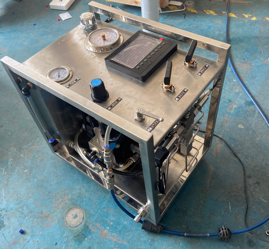
Composition and principle of pneumatic liquid booster pump
Pneumatic liquid booster pump uses gas pressure as a power source Apply pressure amplification to various non corrosive liquids
The pneumatic liquid booster pump assembly should be divided into three parts: 1. reversing valve part 2. driving cylinder part 3. booster cylinder part. Directional valves are divided into valve cores and valve covers The seal is sealed with 12 sealing rings When gas is introduced into the directional valve The valve core will be controlled by a firing pin to swing back and forth Enable the booster pump to drive the piston to continuously reciprocate. The cylinder diameter of the driving cylinder is usually divided into 160mm, 120mm, 100mm, and 80mm. Similarly, the larger the cylinder diameter under the same boost ratio, the greater the flow rate of the booster pump The boosting ratio of a pneumatic liquid booster pump is determined by the ratio of the driving cylinder piston to the boosting cylinder piston. For example, if the ratio of the driving piston to the boosting piston is 4:1, then the pneumatic liquid booster pump is a 4x booster pump. The booster cylinder assembly should have an imported check valve The outlet check valve is composed of a small piston and a cylinder end cap The function of the imported one-way valve is to prohibit the backflow of liquid when it is sucked into the booster cylinder The function of the one-way valve at the outlet is to prohibit the liquid from flowing back to the boosting cylinder after the boosting output.
The principle of pneumatic liquid booster pump is When gas enters the directional valve, it controls the reciprocating motion of the directional valve To control the gas entering both ends of the drive cylinder When the driving gas drives the large piston to push the small piston back and forth, it generates high pressure due to the difference in area The high-pressure plunger controlled by a one-way valve continuously discharges the liquid, and the outlet pressure of the booster pump is related to the air driving pressure (recommended driving pressure 3-8 bar). The output air pressure can be infinitely adjusted by driving the air pressure. When the pressure between the driving part and the output liquid part reaches equilibrium, the booster pump will stop running and no longer consume air. When the output pressure drops or the air drive pressure increases, the booster pump will automatically start running until it reaches pressure balance again and then stop automatically. Gas liquid booster pumps are divided into single pole inlet pneumatic hydraulic pumps, double pole inlet pneumatic hydraulic pumps, three-stage inlet pneumatic hydraulic pumps, single acting inlet pneumatic hydraulic pumps, and double acting inlet pneumatic hydraulic pumps.
Legal statement: The above content belongs to the copyright of Taizhou Feentor - Plagiarism will be prosecuted
相关推荐:ZTG series gas-liquid booster pump
