
Mobile phone: 18815239758 (same as WeChat)
Phone: 0576-89881178
Phone: 0576-89825885


Principle of gas pressurization equipment for gas booster pump
Many customers have questions about how to provide customers with a more intuitive view of the output pressure, inlet pressure, and driving pressure of the gas booster pump without a pressure gauge or switch. The emergence of gas booster equipment can better help customers eliminate these troubles;
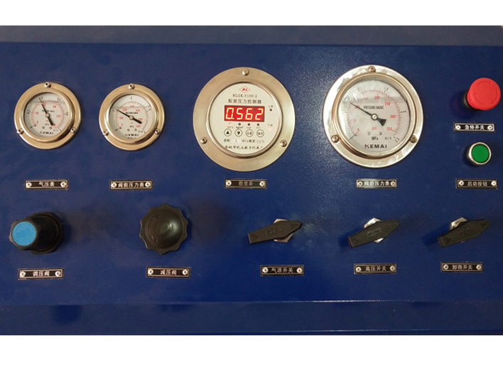
The configuration of gas pressurization system can be roughly divided into the following parts
1. Drive pressure gauge - display the gas source pressure at the customer's site
2. Drive gas source switch - ball valve for gas source switch, closing and opening gas source
3. Intake pressure gauge - displays the pressure at the inlet of the pressurized gas
4. Inlet needle valve or ball valve - used to cut off the inlet pressure of low and high pressure
5. High pressure output pressure gauge - displays the pressure of the gas after pressurization
6. High pressure cut-off valve - the pressure cut-off function for output
7. Unloading valve - After testing, the pressure inside the pipeline pressure vessel is released
8. High pressure pipeline - carrying out internal circuit transportation of high-pressure gas
9. Filter - Filter impurities from the intake air source
Let me show you the layout diagram of the gas boosting system below
The typical circuit diagram of the gas boosting system is as follows
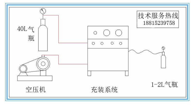 Gas pressurization system
